
Parametric Constructive Solid Geometry
Define your models explicitly with an expressive and ubiquitous programming language.
Note: this package is intended to be used with Linux & GCC.
Note: this package is intended to be used with Linux & GCC.
#include "model.h"
model(example_2)
{
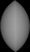
intersection();
sphere(10);
translate(-5, 0, 0);
sphere(10);
translate(5, 0, 0);
end();
save_stl("/tmp/example_2_mesh.stl", .25, 5);
}
#include "model.h"
model(example_3)
{
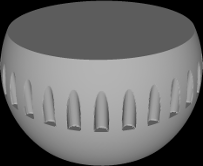
difference();
sphere(10);
plane(0, 1, 0, 5);
plane(0, -1, 0, 5);
for( double i = 0.0; i < 1.0; i += 1.0 / 32.0 )
{
cone(0.5, 0.5, 6);
translate( sin( i * PI2 ) * 10 ,0 , cos( i * PI2 ) * 10 );
}
end();
save_stl("/tmp/example_3_mesh.stl", .25, 5);
}
The programming language used to define the model is C. Running make creates executables in the "./user" directory corresponding to the source files in the same directory. Running these executables produce the STL output files. If you are using model files from untrusted sources it is highly recommended that you review the code before compilation.
There are a myriad of C tutorials explaining how to use for loops and so on, so if you are new to C you might find it useful to reference some of them. However, there is no need to fully understand the language to be proficient at modeling with C-CSG.
Defining a model is accomplished by using "compound objects" in combination with simple objects, often nested. For example:
union(); //this is the beginning of a compound object definition.
    sphere(10); //this is the first object contained within the compound object, a sphere with a radius of 10
    translate(0,10,0); //this translation moves the sphere 10 units on the y axis
    box(); //this object is also contained within the compound "union" object, it is a 1x1x1 box centered on the origin
    intersection(); //this is the beginning of another compound object contained within the original "union" compound object
        sphere(1);
        translate(-2,0,0); //this moves the object -2 units on the x axis
        sphere(1);
    end(); //the intersection object definition is closed
    sphere(2); //this object belongs to the original union compound object
    translate(20,0,0); //this translation is applied to the sphere
end(); //this closes the union compound object, and any objects that might follow do not become part of it.
rotate(0,PI,0); //this transformation rotates the compound object around the y axis.
All compound objects must eventually be closed by a trailing end(), objects that are specified before the end() are contained within it. Transformations can be applied to compound objects before the containing objects are added, or after being closed with end() or both.
The default world space has the y-axis up and all trigonometry and rotation functions use radians.
All *.c files in the project directory will be compiled automatically when make is run, and included in the resulting executable, so editing the makefile is not necessary.
The contained objects define a solid only where they all overlap.
The contained objects are grouped together as one.
The first contained object is cut by every following object.
r is the radius.
sphere(10);
Defaults to 1x1x1 centered on the origin. Use the scale function to size, or use the cube(d) macro.
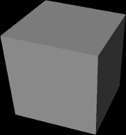
box();
x,y,z defines the normal, and d the distance from the origin. Generally it should only be used in a difference to cut other objects because it is infinite.
plane(0,1,0, -0.5);
r1 and r2 define the radius of each end, and d defines the distance between the end points. The first radius is created at the origin and the second radius is created at y=d. Convenience functions cylinder(diameter, y_height) and pipe(outer_diameter, inner_diameter, y_height) macro use the cone object and center it on the y-axis.

cone(5,10,20);
Uses a 2d polygon to define a circular object where point_list is an array of doubles of the form {x1,y1,x2,y2,x3,y3,...} and point_list_length is the element count, eg. {3,6,8,9} = 4. r is the inner radius.
double k[]={0.9,0.0, 0.9,4.5, 1.2,4.5, 1.0,1.4, 1.2,0.0};
sweep(len(k), k, 8.0);
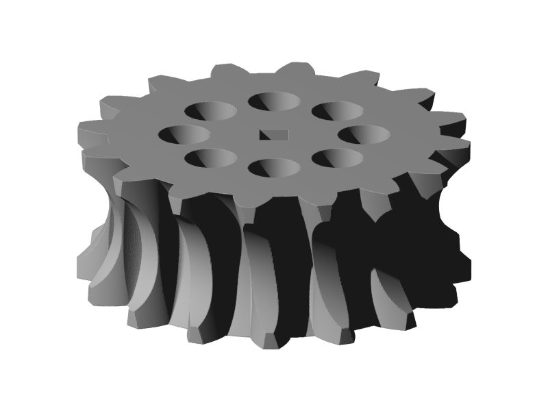
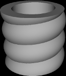
Uses a 2d polygon with y coordinates between 0 and 1 to define a twisting shape, eg. screw threads. Distance is the height of the shape, twists is the number of rotations that the polygon will sweep through before reaching the specified distance. Negative values for twist can be used to make counter-clockwise threads.
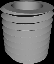
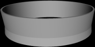
double m[]={3.0,1.0, 4.0,1.0, 5.0,0.5, 4.0,0.0, 3.0,0.0};
lathe(len(m),m,10,8);
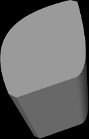
Uses a 2d polygon and a depth value to create an extruded object.
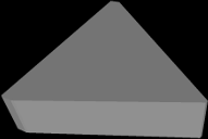
double k[]={0.9,0, 0.9,4.5, 1.2,4.5, 4.6,1.4, 1.2,0};
extrude(len(k), k, 1.0);
Uses a 2d polygon made from straight lines and quadratic beziers to create an extruded object. The point_list is formatted like so: x,y,control_x,control_y,x,y,control_x,control_y,x,y... The final point must equal the first, and straight lines should have their control points set to the value of QUAD_LINE. Note: the bezier curves will be clipped to the internal polygon consisting of all the points if the control point intrudes too far in upon another part of the curve.
double q[]={0.9,0.0, -2,2.2, 0.9,4.5, QUAD_LINE,QUAD_LINE, 1.2,4.5, 3.0,2.0, 2.6,1.4, QUAD_LINE,QUAD_LINE, 1.2,0.0, QUAD_LINE,QUAD_LINE, 0.9,0.0};
extrude_quad(len(q),q,4);
Creates a group of extrude_quad objects using the specified utf8 encoded string and a path to a ttf font. Because the dimensions are variable depending on the font it is often helpful to use the dimensions function to scale it appropriately.

text("Hello World!","/usr/share/fonts/truetype/droid/DroidSerif-Bold.ttf",4.5);
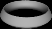
Uses a 2d polygon made from straight lines and quadratic beziers to create an object of the same nature as the lathe object.
double q[]={3.0,1.0, QUAD_LINE,QUAD_LINE, 4.0,1.0, 5.0,0.5, 4.0,0.0, QUAD_LINE,QUAD_LINE, 3.0,0.0, QUAD_LINE,QUAD_LINE, 3.0,1.0};
lathe_quad(len(q),q,8,3);
Uses a 2d polygon made from straight lines and quadratic beziers to create an object of the same nature as the sweep object.
double q[]={0.9,0.0, -2,2.2, 0.9,4.5, QUAD_LINE,QUAD_LINE, 1.2,4.5, 3.0,2.0, 2.6,1.4, QUAD_LINE,QUAD_LINE, 1.2,0, QUAD_LINE, QUAD_LINE, 0.9,0};
sweep_quad(len(q),q,8);
Defines a non-solid interior for the enclosed objects.
#include "model.h"

int my_interior_noise(double *local)
{

    // use three octaves
    double v0,v1,v2;

    v0 = open_simplex_noise3(osctx,  local[0] /2.0, local[1]/2.0 ,  local[2]/2.0);
    v1 = open_simplex_noise3(osctx,  local[0] / 4.0, local[1] / 4.0,  local[2] / 4.0);
    v2 = open_simplex_noise3(osctx,  local[0] / 8.0, local[1] / 8.0,  local[2] / 8.0);

    double v = v0+v1+v2;

    if(v>=-1.0 && v<=0.4) //arbitrary range is solid
        return 1;

    return 0;
}


model(noise_test_1)
{
    interior(my_interior_noise);
        sphere(5);
        sphere(5);
        translate(5,0,0);
    end();

    save_stl("/tmp/mesh.stl", .25/6, 5);
}
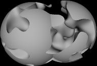
Moves the surface of enclosed objects according to the user defined noise function, the padding value is used to expand the bounding box and should be at least equal to the maximum deviation that the noise function applies to the object.
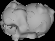
#include "model.h"

void my_exterior_noise(double *local)
{
    // use three octaves
    double v0,v1,v2;
    v0 = open_simplex_noise3(osctx,  local[0] /2.0, local[1]/2.0 ,  local[2]/2.0);
    v1 = open_simplex_noise3(osctx,  local[0] / 4.0, local[1] / 4.0,  local[2] / 4.0);
    v2 = open_simplex_noise3(osctx,  local[0] / 8.0, local[1] / 8.0,  local[2] / 8.0);

    double v = v0+v1+v2;

    if(v>=-1.0 && v<=0.4) //if the noise is in this range we move the point passed to us
    {
        local[0]+=v;
        local[1]+=v;
        local[2]+=v;
    }
}


model(noise_test_2)
{

    exterior(my_exterior_noise, 1.0);
        sphere(5);
        sphere(5);
        translate(5,0,0);
    end();

    save_stl("/tmp/mesh.stl", .25/6, 5);
}
Scale current object.
Move current object.
Reset transforms for current object. Can be used to remove transformations from a previously copied object.
paste(o);
identity(); //scaling, and rotation of copied object are now clear
Rotate current object by x, y, and z in that order.
Mirror current object. The same thing can be accomplished using scale(x,y,z) with negative values .
Mirror current object.
Mirror current object.
Rotate an object by angle a along an arbitrary axis defined by x,y,z.
If an integer 1 is set for x, y, or z the axis will be inverted.
Changes from a y-up world to a z-up world. Useful to set just prior to exporting an STL file.
This function is required to follow a compound object to indicate the end of the enclosed objects.
Changes the values in the variables pointed to by cx,cy,cz to the width, height, and depth of the bounding box, generally useful for resizing text and aligning objects without prior knowledge of their general size.
double plate_cx = 60.0;
double plate_cz = 25.0;
double text_border = 5.0;
double text_cx,text_cy,text_cz;

difference();

    box();
    translate(0,-0.5,0);
    scale(plate_cx,4,plate_cz);

    text("C-CSG","/usr/share/fonts/truetype/droid/DroidSerif-Bold.ttf",4.5);

    //center text on plate
    dimensions(&text_cx,&text_cy,&text_cz);
    translate(-text_cx/2.0,-4,-text_cz/2.0); //center text on zero
    scale((plate_cx-(text_border*2.0))/text_cx,1,(plate_cz-(text_border*2.0))/text_cz);  //scale to correct size to fill plate minus the border padding

end();
Removes the current object and children from the model and returns it.
intersection();
    sphere(10);
    translate(-5,0,0);
    sphere(10);
    translate(5,0,0);
    sphere(10);
    translate(0,0,-5);
    sphere(10);
    translate(0,0,5);
end();
OBJECT my_var = cut(); //removes current object (the intersection and contents) from the model and stores it in the variable "my_var".
Duplicates the current object, with its existing transform.
    sphere(10);
    translate(5,0,0);
    dup();
    translate(-10,0,0); //two spheres, one is at x=5 and one is at x=-5
Puts a copy of the stored OBJECT into the model.

intersection();
    sphere(10);
    translate(-5,0,0);
    sphere(10);
    translate(5,0,0);
    sphere(10);
    translate(0,0,-5);
    sphere(10);
    translate(0,0,5);
end();

OBJECT my_var = cut();

difference();
    sphere(10);
    paste(my_var);
    translate(0,5,0);
    paste(my_var);
    translate(0,-5,0);
end();
Exports the model as a triangle mesh using the specified number of CPU threads and the specified resolution (0.3 is a good starting point if you're working in mm for 3d printing).